Saturday, February 20, 2010

Lessons In Electric Circuits

Lessons In Electric Circuits -- Volume V


Chapter 9


CIRCUIT SCHEMATIC SYMBOLS


Wires and connections


Older electrical schematics showed connecting wires crossing, while non-connecting wires "jumped" over each other with little half-circle marks. Newer electrical schematics show connecting wires joining with a dot, while non-connecting wires cross with no dot. However, some people still use the older convention of connecting wires crossing with no dot, which may create confusion.


For this reason, I opt to use a hybrid convention, with connecting wires unambiguously connected by a dot, and non-connecting wires unambiguously "jumping" over one another with a half-circle mark. While this may be frowned upon by some, it leaves no room for interpretational error: in each case, the intent is clear and unmistakable:


Power sources


Resistors


Capacitors


Inductors


Mutual inductors


Switches, hand actuated


Switches, process actuated


It is very important to keep in mind that the "normal" contact status of a process-actuated switch refers to its status when the process is absent and/or inactive, not "normal" in the sense of process conditions as expected during routine operation. For instance, a normally-closed low-flow detection switch installed on a coolant pipe will be maintained in the actuated state (open) when there is regular coolant flow through the pipe. If the coolant flow stops, the flow switch will go to its "normal" (unactuated) status of closed.


A limit switch is one actuated by contact with a moving machine part. An electronic limit switch senses mechanical motion, but does so using light, magnetic fields, or other non-contact means.


Switches, electrically actuated (relays)


Connectors


Diodes


Transistors, bipolar


Transistors, junction field-effect (JFET)


Transistors, insulated-gate field-effect (IGFET or MOSFET)


Transistors, hybrid


Thyristors


Integrated circuits


Electron tubes


Lessons In Electric Circuits copyright (C) 2000-2010 Tony R. Kuphaldt, under the terms and conditions of the Design Science License.

Friday, February 19, 2010

Plug n Play Cables

Plug n Play Cables are made for the Alinco
DR-135T 144 MHz , Alinco DR-235T 220 Mhz and the Alinco DR-435T 440 Mhz radios
to be interfaced with the IRLP Version 3.00 Board.
Source from : http://www.irlpcables.com/


The male DB9 connector connects to the back of

the Alinco
radio.The female DB9 connects to the

IRLP interface board.


The two 1/8
inch stereo connectors are clearly


marked and plug into your IRLP node soundcard.


The
Alinco DR-x35 series radios have a female DB9


connector on the back. When you use a Plug n Play

cable, all the interface connections from the IRLP

board to the radio are made through this connector.

These radios work great for IRLP nodes.


NOTE:
Please check the jumper settings on the


IRLP interface board to make sure that

COS DETECT is set to LOW.


Cables for other radios and or kits are available on special
request,


For Ordering information please contact Marshall, ke6pcv via email at:


ke6pcv@cal-net.org


PLUG n PLAY CABLES


Copyright 2007 IRLP Cables Web
Design & Host


Last Updated

September 17, 2008


13.8V 20A linear power supply


13.8V 20A linear power supply


Source from: http://ludens.cl/Electron/Ps20/Ps20.html

Linear power supplies for communication equipment are among the most commonly
built electronic projects. Almost every technically inclined radio amateur
has built at least one. But unfortunately most designs, even those published
in well respected books, are unnecessarily complicated, or have some specific
drawbacks. The design presented here is a little bit unusual in its arrangement,
but offers some advantages over the usual designs that I will explain in
the following paragraphs.


Basics of linear power supplies


First, let's start from the basics: A linear power supply has a transformer
that steps down the line voltage to some voltage that is higher than what
will be required at the regulated output. Then a rectifier and a filter
capacitor transform the low voltage AC into a moderately filtered DC that
still is unregulated and has some ripple. Finally, a regulating circuit
"burns off" the excess voltage, leaving only the exact amount desired at
the output, typically 13.8V for communication equipment.

One typical mistake made by many amateur designers is using a transformer
that has a voltage that's too low for the combination of rectifier, filter
and regulator used. The situation is this: You need 13.8V at the output
at all times. Your regulator eats up a certain minimum voltage, which depends
on its design. Many regulators need at least 2V across them, so you need
15.8V minimum at the worst time across the filter capacitor. This is the
voltage at the minimum point of the ripple waveform, but the capacitor
needs to be charged to the maximum of this ripple voltage. So, the size
of the capacitor defines how much additional voltage you need for this.
A 60000uF capacitor, used at 20A, and discharging during almost a half
cycle at 50Hz (10ms), will drop the voltage by almost 3.3V. So, you need
to charge the capacitor to at least 19.2V under the worst conditions! If
you are using a bridge rectifier made from silicon diodes, which loose
about 1.2V each at peak current, then you end up having two diodes conducting
at the time of charging the capacitor, dropping a total of 2.4V. So, the
transformer needs to develop 21.6V peak voltage. This happens under heavy
load, as most of the charging of the capacitor happens during a very short
time, so there is a lot of voltage drop in the transformer, maybe 10 to
15%, depending on its size. So, you need to consider a transformer that
develops about 24 or 25V peak voltage. Finally, you need to consider that
the power line from which your design gets its power is not 100% stable!
Allowing for 10% worst case sag in the power line, you end up needing a
transformer that at nominal line voltage and small load provides about
27V peak! That would be 19V RMS.

If you use a transformer with a lower rating, or a smaller filter capacitor,
or a regulator that has a minimum drop of more than 2V, then your power
supply will loose regulation under some conditions. Many amateur designers
run into this problem.

On the other hand, if you use a regulator with a lower drop, and/or
a larger filter capacitor, then you can slightly ease the transformer voltage
requirements. This can be very useful to keep the filter capacitor voltage
rating requirement at 25V, since otherwise you would be forced to use a
35V capacitor, which is much larger and more expensive. A lower transformer
voltage is also an advantage from the efficiency point of view. After all,
the complete excess voltage has to be burned off by the regulator, causing
a huge power loss and requiring a large heat sink!

Another issue is what kind of pass elements to use for the regulator.
MOSFETs are not a good choice, because they are much more expensive than
bipolar transistors for a given minimum voltage drop and power dissipation.
So, almost every power supply uses bipolar transistors. NPN transistors
are usually preferred over PNP ones, because they are cheaper for a given
performance, and there is wider selection. So far, so good. But most designers
place their pass transistors on the positive side, in emitter-follower
fashion, adding a Darlington driver (or two Darlington stages). This is
a very bad choice for several reasons: One, each transistor connected in
that way produces a minimum voltage drop of 0.6 to 0.7V. A three-stage
arrangement, as is often needed, would have a minimum drop of around 2V,
plus the drop caused by any equalizing resistors! Also, the transistor
collectors, which are connected to the cases, are at the unregulated positive
voltage, and thus require insulation from the heatsink and power supply
case. The necessary mica insulators add a huge amount of thermal resistance,
making it much harder to cool the transistors properly.


This design


In the power supply presented here, several measures were taken to get
rid of the problems mentioned above. The pass transistors are located in
the negative rail and connected in common-emitter configuration rather
than as emitter-followers. Thanks to this, the regulator's minimum voltage
drop is extremely low, only about 0.1V for the transistors plus 0.5V for
the equalizing resistors. The other advantage is that the collectors are
directly connected to the negative pole of the power supply's output, which
in most applications is grounded. That means that no insulation is required
between the transistors and the grounded power supply cabinet! This eases
the cooling very considerably. Thanks to the low regulator drop, a low
cost 25V filter capacitor can be used.

The voltage adjustment potentiometer is arranged in such a way that
if the wiper contact fails, the voltage will go down, never up. This is
an important safety issue, avoiding damage to connected equipment.

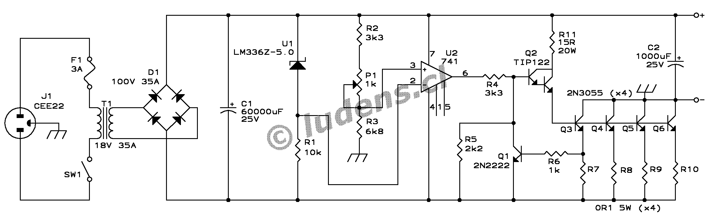
Here is the schematic diagram: Use the full resolution
version
for printing.


This power supply delivers a highly regulated 13.8V, adjustable over
a moderate range, at a continuous current of up to 20A. It is current-limited
to approximately 25A, and short circuit protected for as long as the heat
sink can keep the transistors cool enough. It is probably the simplest
design that can accomplish this.

Some notes about this circuit:

- Use a transformer for the primary voltage you need. The 3A fuse is
for 220 or 240V primaries. If you use something in the neighborhood of
110V, use a 6A fuse.

- The rather high transformer rating of 35A accounts for the losses
that occur due to the capacitive input filter. If your transformer is rated
for capacitive input, then a 25A value is enough.

- Of course you can make up C1 by placing several smaller capacitors
in parallel. Likewise, the 0.1 Ohm, 5 Watt resistors can be made up by
several in parallel, for example by 5 resistors of 0.5 Ohm, 1 Watt each.

- The LM336Z-5.0 voltage reference IC should not be replaced by a zener
diode. Zeners are not nearly as stable. A different voltage reference IC
can of course be used, if R2 and R3 are modified for the different voltage.

- D1 and Q2 through Q6 need heatsinking. Only Q2 needs insulation. D1
dissipates up to 60W, Q2 up to 25W, while the pass transistors dissipate
up to 30W each in normal use, but may reach a level of 130W during short
circuit! Take this into account when choosing the heat sink!

- R5 exists only to make sure that the transistors can actually be driven
off. The 741 is not a single-supply operational amplifier, so it cannot
drive its output very low. If a true single-supply opamp is used, then
R5 becomes unnecessary.


How it works


U1 provides a regulated reference voltage that's always 5V below the positive
rail. U2 compares this reference voltage to a sample from the output (ground
against positive rail) and drives a Darlington transistor connected as
emitter follower, which in turn drives the four pass transistors connected
in common emitter configuration. Four resistors equalize the current through
the transistors, and one of these resistors does double duty by serving
as current sense resistor. If the current through this resistor exceeds
about 6A, then Q1 will start conducting, swamping the drive from U2 to
the negative rail and thus limiting the output current.

No parts were added to control frequency response, loop damping, etc.
All trust was placed on the 741's rather low frequency response and high
stability, combined with a 1000µF capacitor across the output. In
practice this has proven to work well enough, but purists may want to experiment
with the loop response and add some compensation capacitor.


Construction notes


A power supply like this is simple to build, but it uses large and heavy
parts, so physical construction should be strong. The 630VA transformer
is heavy, and even the heat sink will not be small. So, build or buy a
good, solid, sturdy cabinet. Try to use aluminum for the cabinet, since
steel will vibrate from the transformer's stray field. The cabinet should
be very well ventilated.

The heat sink needs to be large. How large...? Well, it
depends. Do you want your power supply to be short circuit protected without
a time limit? That will require a really large heat sink!

In normal use at the 20A level there will be about 200W dissipation.
The diode bridge can run at 35A when kept cool at 25 degrees Celsius (which
is utopic, by the way!). As silicon can withstand 150


degrees before melting down, the 35A bridge running at 20A can survive
about 75 degrees case temperature. The pass transistors are rated for 115W
at 25 degrees, which means that at 30W each they can run safely at almost
120 degrees. The driver transistor can dissipate 60W at 25 degrees, so
at 25W it may heat up to 98 degrees.

The thermal resistance from the bridge to the heat sink is probably
better than 0.2 degrees per Watt, so the bridge is happy if the heat sink
stays below 65 degrees. The power transistors probably have around 0.5
degrees per Watt of thermal resistance to the heat sink, so they need the
heat sink to stay below 105 degrees or so. Easy. The limiting factor in
this case is the driver transistor, because it needs to be insulated! That
transistor with its mica insulator will have about 1.5 degrees per Watt
thermal resistance, thus requiring the heat sink to stay below 60 degrees
or so. You may want to replace the TIP122 by a Darlington transistor having
a higher power rating, so the bridge would become the limiting factor.

In the above case, you need a heat sink that doesn't warm up to more
than 60 degrees Celsius while dissipating 200W. If you consider a highest
ambient temperature of 30 degrees, then the heat sink may heat up only
another 30 degrees above ambient. That is a thermal resistance of 0.15
degrees per Watt, which means a HUGE heat sink! If you really want to run
this power supply at 20A continuous duty, you may be better off with a
more moderate (still large) heat sink plus a small fan that blows air through
it!

You may use a rather small heat sink, rated for 0.7 degrees per Watt
or so, if you will use this power supply for a typical HF transceiver that
needs 20 to 23A peak, but at an average of no more than 5A or so. This
is what many commercial power supplies do.

If you use a small heat sink, and run the power supply at high average
current, you WILL burn it up. Take my word for it. Too many people have
blown up their power supplies in this way.

Just for fun, lets see how much the heat sink requirement increases
if you want protection against continuous short circuit. The total power
dissipation would be around 550W. The bridge and driver transistor would
run much like they would at 25A load, while the dissipation in the pass
transistors is hugely higher than normal, reaching about 130W! As the 2N3055
is rated for 115W at 25 degrees, it means that the transistor cases would
have to be kept below 9 degrees! Considering the 0.5 degrees per Watt of
thermal resistance between each transistor and the heat sink, the heat
sink would need to stay below -56 degrees Celsius! A giant heat sink running
at the south pole maybe could just do the job, otherwise you would need
a cryogenic system! Needless to say, it is impractical to implement indefinite
short circuit protection in this way! It would become practical if you
increased the number of pass transistors, increasing proportionally the
equalizing resistors' values, but even then it would require a large heat
sink. A foldback current limit would overcome this problem, but it brings
along other problems of its own, like the power supply shutting down when
charging a capacitor in some equipment. I believe that the best compromise
is to build this circuit as shown, using a reasonably oversized heatsink,
and shut it off quickly when a short circuit happens, before the transistors
can overheat. After all, a 25A short produces a spark that's obvious enough
to notice!


A note on R11


I originally did not have R11 in the design. A fair number of readers built
the power supply and had good results. But then I got a mail from Carl
Ressel, who built it and tried it out feeding a variable voltage onto C1.
Very reasonable, only that without R11, Q2 took a very high current while
the input voltage was too low to allow the supply to produce normal output!
This situation could be fatal for Q2 in the event of a brownout. With the
added R11, the problem is solved. This shows how easy it is to overlook
a situation that normally does not happen, but sometimes can! A good design
must be able to handle any situation. Thanks, Carl, for this test!


I did not make a printed circuit board. Anyway, the transformer, fuse,
switch, connectors and filter capacitor are mounted to the case, while
the 5 power transistors, the 4 large equalizing resistors and the rectifier
bridge are mounted on the heat sink. This leaves so few components available
to mount on a board, that it doesn't pay to make a PCB. I suggest you mount
the remaining components on a piece of perfboard.

The quality of the voltage regulation depends mainly on how you build
this project. The single most important factors for good regulation are
that the ground connection of R3 must go DIRECTLY to the negative output
connector, while the top of R2 and of U1 must go directly to the positive
output. Everything else is less important.

I suggest that the case is connected to the negative output ONLY via
the pass transistors' cases, in order to avoid any ground loops.

This is a nice beginner's project, as all components are easily available
all over the world, the cost isn't extreme, the circuit is very simple,
and the resulting power supply will be useful for an entire ham radio career.
For more advanced builders, I suggest to try the 40A
switching power supply
, which is much more elegant, efficient, powerful,
smaller and lighter, costs about the same to build, but is much more complex.

Ten Dollar Miracle Whip Clone

Ten Dollar Miracle Whip Clone
Source from: http://kl7r.ham-radio.ch/

Ten Dollar Miracle Whip Clone


I bought a 6 foot whip and 25 ohm rheostat at radio shack and wired them up like this:


----
\ / 6 foot whip
\/
|
|
\
/
rf in ----->\ 25 ohm radio shack rheostat
/
\
|
---
/// gnd


I did some experiments with it ( off a quarter mile with my xyl reading base rig
s=meter back over 2 meters).

Here are HFPACK thread discussions about it:


----------------------

Date: Tue Dec 30, 2003 1:27 am
Subject: 1500 miles on $5 homebrew Miracle Whip

I talked to KQ6XA yesterday standing in my back yard running
an FT817 on battery power at 5 watts. I live in Juneau
Alaska. That is 1525 miles (2454.46 km)

This was on the HFPACK freq of 18.157.5 USB.


My home brew miracle whip:

6 foot RadioShack extendable whip
(I forget what this cost- you could use a tv antenna whip)

25 ohm RadioShack wirewound potentiometer (rheostat) (about $3)

A piece of circuit board to mount the pieces (junkbox)
An SO239 (female PL259) (junkbox)
A male to male pl259 (junkbox)


Circuit:
Not much to it.
Drill a hole for the center of the 239 in the circuit board
Solder the shield of the SO239 to the circuit board
Drill a hole and mount the rheostat

Center pin from SO239 goes to center connector (wiper)of rheostat.
Shield of SO239 goes to bottom connector of rheostat
Antenna goes to top connector of rheostat

make sure the antenna is insuated from the circuit board and
bind it to the circuit with some tiewraps

I can put up a picture if anyone is interested.


Comments:


The rheostat acts like an autotransformer at RF frequencies.
I am always able to get a 1:1 match on it.
It tunes so easily that I think it is part dummy load and part
autotransformer.

(Ever try using a 100 watt lighbulb as an autotuner? Ive done
it. Its a bit frightening but it works.)

I used a big electrician's wirenut as a knob for the rheostat

I can put up a picture if anyone is interested.

[Mike KL7R]


--------------------------

Mike,

Please send or post the pics for the antenna.

You could email them to me directly.

73

Fritz
WD9FMB

---------------------------

Mike, I would love to see a picture of the homebrew
miracle whip. Rusty de KC0LMS

---------------------------

Sounds like a real leaky dummy load to me.

Al, N8ARO

---------------------------


> Sounds like a real leaky dummy load to me.

I remember my elmer telling me that when he was waiting for his
novice license, he practiced sending CQ into a light bulb and
someone in the states came back to him on his light bulb!

---------------------------

>
> > Sounds like a real leaky dummy load to me.
>
> I remember my elmer telling me that when he was waiting for his
> novice license, he practiced sending CQ into a light bulb and
> someone in the states came back to him on his light bulb!

I've heard this hundreds of times but how do you actually do it?
Just pump the transmitter output into a light socket? No matching
network or resistance required? Is the bulb rating equal to the out
put of the rig, i.e. 100w rig = 100w bulb?

MarkF
K1MKF

---------------------------

> K1MKF wrote:
>> kl7r wrote:
>> ...sending CQ into a light bulb ...
> I've heard this hundreds of times but how do you actually do it? ...

No, don't do it. That was in the tube days.
Nowadays it would blow the finals. You could use a 50 ohm dummy load
though and accomplish the same trick, as coax wil radiate. My guess is
that you won't get out much on ladder line into a purely resistive load
though. There is a nice article on RF, coax, baluns, etc. In the recent
QEX.

We used a light bulb for a while but switched to a parallel fan-like
cluster of 10 500 ohm 10 watt resistors (not wire would as they would be
inductive) to give 50 ohms at 100 watts, and them immersed that in a
gallon paint can filled with transformer oil acquired from a neighbor at
the power company so it could take more power. I remember seeing it
bubbling out during a VHF tune-up with an old tube-type Motorola X53GGT
2m transmiter. I shudder now to think what was in the transformer oil,
but it was the early 1970's so I don't know for sure.

Leigh
WA5ZNU


-------------------

>
> I've heard this hundreds of times but how do you actually do it?
> Just pump the transmitter output into a light socket? No matching
> network or resistance required? Is the bulb rating equal to the

Yes thats what I did one day. Ran coax to a litebulb socket.
It is a bit frightening on a solid state rig. The swr spikes
up (ie a dead short) when you first start transmitting
but when the filament starts glowing white after a second or so
the swr drops down to 1:1.

I paralled my loop antenna across the light bulb and
was able to use it on multiple bands with the same effect.

I quit after a night of experimenting and proving to the
guys on my favorite net that it worked.

I dont think I would recommend this if you have a solid
state rig. A tube type final can handle the swr spike a bit
better than a solid state rig.

KL7R


------------------

> I've heard this hundreds of times but how do you actually do it?
> Just pump the transmitter output into a light socket? No matching
> network or resistance required? Is the bulb rating equal to the out
> put of the rig, i.e. 100w rig = 100w bulb?
> ....

I can't imagine sending in much power with solid-state finals, even
with a tuner, as its a very small inductor in series with a resistor
that changes dramatically in value with applied power and time. I've
only ever heard of it done with tube rigs to the point of lighting the
bulb. At low enough power, though, one could combine a few bulbs in
series and parallel to get to 50 ohms with some inductive reactance,
and be fairly stable as long as you never put out enough current to
raise the temperature of the filaments significantly.

73,
tim

-----------------------

> I can't imagine sending in much power with solid-state finals, even
> with a tuner, as its a very small inductor in series with a resistor
> that changes dramatically in value with applied power and time.

Thanks for all the replies. I think I'll just stick with my trusty
MFJ dummy load and some cheap coax.

MarkF
K1MKF

--------------------

Hey Mike we have been kidding you about the Dummy Load Antenna, however, it
does sound simple and interesting.

Could you run some field strength testing sometime at different SWR
settings. A 1:1 SWR may be all resistive from the rheostat and you may
radiate more RF at a greater SWR. Just a thought.

Al. N8ARO


--------------------------

Al I am planning to do some A/B testing of the rheostat MW
and a same sized whip with a BLT tuner. The idea of using a
field strength meter is a good one. Maybe my wife who is
also a ham could be my "field strength meter". That way I
could go out of the near field of the antenna and see how
they act a bit further out.

A note here to all:

I must give credit to Bonnie KQ6XA.

She made a version of this antenna before I did that did pretty
well in the antenna shootouts.
The original article in QST mentioned using a rheostat body
as the wiper which contacted the autotranformer toroid.
I thought since the rheostat is inductive at rf that you could
just use the rheostat itself and so went to radio shack to
look for wirewound pot.
Before I got my version of the MW built, I found Bonnie's version
in the HFPACK shootouts which also uses a rheostat -just a much
larger one. Interestingly her version (called a Wonder Whip)
did pretty well in the 2002 hfpack antenna shootout - only down
half an S unit from a full sized vertical.

Check out:
http://www.qsl.net/hfpack/antennas/shootoutvertical2002.html

-------------------

I went out tonight (PS it is 5 above here gorgeous and clear).

I took out the radioshack rheostat MW and a NORCAL BLT with a
duplicate whip attached to one leg of the norcal blt and the other
leg of the norcal blt shorted to ground.

I walked about a quarter of a mile away from our house and setup
both antennas (the 6'MW with a 25 ohm rheostat and BLT/6'whip)

I had my wife via 2 meters read me back S-meter readings on my
base rig.

The Rheostat mw did much worse than the BLT whip.
S6 vs S1 !
So I guess it is mostly dummyload :(

I did try a near field test of SWR vs field strength.
The fieldstrength seemed greatest when the SWR was "2 bars" [on my f817].
After dropping the swr to zero, if you kept turning the pot
fieldstrength would drop. In the far field there was no noticable
difference in the SWR setting vs field strength.

So it appears that if you get a broad null, the best position
of the pot should be at where it just hits "no bars" and
no farther.

A lower ohmage rheostat would have less resistive loss
but I dont know where to find a low value rheostat locally.

Hey, The good news is that it means I was 30 db down from a 6 foot
whip and a BLT and still was able to talk 1500 miles.


So the plan now is to remove the nichrome wire and replace
with #30 magnet wire and see what happens. My radio shack
store has 3 or 4 more of the 25 ohm rheostats in case there
no improvement or if I crater the current one.


Mike
KL7R

---------------------------

I pulled apart the rheostat and pulled off the nichrome wire
and wrapped the core with #30 magnet wire then sanded the inside
of the wire to expose the bare wire.

The receiver peaks are much sharper now
The transmitter SWR dips are much sharper also.

It seems to need a counterpoise more now.

The resistance of the magnet is about 1.5 ohms so this
version must be nearly completely inductive.

Ill do A/B tests tmw..


--------------------------------------------------

Mike, thanks for sharing all you fun and hard work with us.

Al, N8ARO


----------------------------


I did the A/B tests this morning
After replacing the nichrome wire with #30 magnet wire
the tests showed an improvement but still not as good
as a BLT tuner and whip.

The field strength readings this time were:
BLT/Whip S9
Rheostat body with #30 wire and whip S7

So the homebrew mw is down 12 db instead of the previous 30 db
Or saying it another way:
Replacing the nichrome wire with magnet wire was worth 18db or
3 S-units.

I think Ill quit at this point.
I might try putting an L network at the base of the whip
sometime and see if it comes close to the BLT/whip combination

Thanks for the feedback,
Mike KL7R


---------------------------

I will say that I have used it for QS0s to other parts of Alaska (600+ miles)
and have talked to a fellow walk-about in seattle who was running an ft817 and
a MW. And , as I mentioned at the beginning of this, I did QSO with California
from here in Alaska standing in my back yard with the rig and antenna in one
hand and the mic in another.

I keep the miracle whip in my "qrp bag" I use it (and a 1 foot square
shielded loop) for signal DF-ing. It is cool to take along to the ham club and
use for testing and bragging rights but I dont use it every day. I am a fan
of big wire antennas (big wire loop antennas actually). I actually use an
end fed piece of wire (88 feet) and a BLT tuner for most of my in the field qrp
work.

73 Mike


Radiation Plots

Radiation Plots


Our first plot shows the elevation pattern in both the broadside (white trace) and end fire (yellow trace) directions for a height of 4 wavelengths, or 560 feet. Note the substantial high angle radiation in all directions, in addition to the excellent low angle lobes.


d40a.gif


This plot shows the elevation patterns at a height of 2 wavelengths, or 280 feet.

White trace is broadside. Yellow trace is axial (off the ends).

Still Lots of high angle radiation.


d40b.gif


This plot shows the elevation patterns at a height of 1 wavelength, or 140 feet.

White trace is broadside. Yellow trace is axial (off the ends).

The secondary lobe is down to 47 degrees, but the primary lobe is up to 14 degrees.


d40c.gif


This plot shows the elevation patterns at a height of 0.7 wavelength, or 98 feet.


White trace is broadside. Yellow trace is axial (off the ends).

The primary lobe is up to 20 degrees.

Note the large vertical lobe which has appeared!


d40d.gif


This plot shows the elevation patterns at a height of 1/2 wavelength, or 70 feet.

White trace is broadside. Yellow trace is axial (off the ends).

Now that's a classical dipole pattern!


d40e.gif


This plot shows the elevation patterns at a height of 0.3 wavelength, or 42 feet.

White trace is broadside. Yellow trace is axial (off the ends).

We are entering the "skywarmer" mode here.


d40f.gif


This plot shows the elevation patterns at a height of 0.1 wavelength, or 14 feet.

White trace is broadside. Yellow trace is axial (off the ends).


d40g.gif


This plot shows comparative elevation patterns, in the broadside direction only,

White trace is for 2 wavelengths, 280 feet.

Yellow trace is for 1 wavelengths, 140 feet.


d40h.gif


This plot shows comparative elevation patterns, in the broadside direction only.

White trace is for 0.7 wavelengths, 98 feet.

Yellow trace is for 0.5 wavelengths, 70 feet.


d40i.gif


This plot shows comparative elevation patterns, in the broadside direction only.

White trace is for 0.5 wavelengths, 70 feet.

Yellow trace is for 0.3 wavelengths, 42 feet.

Pink trace is for 0.1 wavelengths, 14 feet.


This page is published by Mike Banz, AA3RL
as a service to the Amateur Radio community.

Please distribute freely.


The author welcomes any questions, criticisms, or compliments via email.


email Mike with comments or questions.


How High should my Dipole be?--2


HeightHeight Fav DirFav Dir End DirEnd Dir
Launch Launch
Wave GainAngle/ GainAngle/ FeedptRes.
LengthsFeet (dbi)Bmwidth (dbi)Bmwidth ZFreq
4.0*560 7.754 / 4 5.5772 / 13 6.93
3.0420 7.835 / 5 5.2568 / 14 77+ j116.94
2.0*280 7.807 / 7 039 / 75 + j126.95
1.5210 7.729 / 10 -2.5033 / 75 + j116.96
1.0*140 7.6414 / 15 -11.0020 / 74 + j086.96
.9126 7.0316 / 17 -8.3022 / 85 + j136.94
.8112 7.1618 / 19 -6.4025 / 84 + j266.88
.7*98 7.9520 / 22 -4.5030 / 70 + j306.88
.684 8.3523 / 26 -1.9540 / 60 + j166.94
.5*70 7.4528 / 33 -0.5143 / 33 71 - j007.00
.456 6.0635 / 47 1.3059 / 102 93 + j046.98
.3*42 5.5950 / 137 4.7190 / 80 100 + j326.86
.228 6.7090 / 118 6.7090 / 67 71 + j566.77
.1*14 8.2190 / 103 8.2190 / 66 23 + j396.84
.057 9.6190 / 99 9.6090 / 72 7 + j126.95


* Elevation plots shown below


Analysis, Favored Direction:


The first thing to notice is that the gain in the favored (broadside) direction varies very little with height. The important change in the broadside pattern occurs in the launch angle of the primary lobe. As the antenna moves closer to the ground, the launch angle of radiation gets higher and the -3 dB vertical beam width becomes broader. Note that below the benchmark height of ½ wavelength, the launch angle increases rapidly. Once the dipole is lowered to 0.3 wavelengths, most of the radiation goes in a vertical direction. This explains the frequently heard "rule" that a dipole must be at least ½ wavelength high to work. The seeming anomaly with the beam width below 0.4 wavelengths is easier to understand by viewing the plots shown below.


Analysis, End-Fire Direction:


One frequently sees a dipole azimuth pattern depicting a very sharp null off of the ends of a dipole. While technically accurate, this can be very misleading as the table above shows, and is a result of trying to depict a 3 dimensional pattern in 2 dimensions. This often seen null is only evident at the same launch angle as the maximum broadside gain. Of major significance is the large amount of gain off the ends at higher launch angles. Due to multiple lobes forming above ½ wavelength, this is not easily shown in tabular form. I have arbitrarily chosen to list gain and launch angle for the secondary lobe with the lowest launch angle, but recognize that there is frequently a stronger primary lobe at higher angles. Consult the plots below for a better visualization.


Analysis, Feed Point Impedance:


The reference antenna length was chosen to resonate at the ½ wavelength height. As expected, the feed point impedance oscillates significantly as the height changes from our reference point. Thus we verify the old adage that you must trim the dipole to fit your particular QTH (height being very important). The corresponding resonant frequency for each height is shown in the last column for reference, since complex impedance's may be of less practical importance to some.


So, How High should the dipole be to work well?


Now we are back to looking at what we want the dipole to achieve.


For DX work, higher placement is warranted, since more power concentrated between 5 and 15 degrees is reported to be of major benefit. Heights around one wavelength are necessary to get the broadside lobe to launch in this range. However, higher may not always be better. Pay careful attention to the magnitude of secondary lobes in the broadside direction, as well as high angle radiation off the ends. Some heights would appear better than others due to concerns with nulling out local QRM. A complete discussion of of this aspect is beyond the scope of this article, but may be investigated at a later date.


For local work, lower heights appear to be more beneficial. Note especially how omni-directional our dipole becomes at lower heights. Below 0.4 wavelengths, there is less than 1 dB of attenuation in the end fire direction, which suggests a height between 0.4 and 0.3 might be an ideal compromise for local nets and rag chewing.


Feed point impedance and matching does not seem to be of major concern except at very low heights. The effect of height on 2:1 SWR bandwidth was not investigated.

How High should my Dipole be?


How High should my Dipole be?


Source from :http://www.qsl.net/aa3rl/ant2.html


Dipole Antennas - the Effect of Height Above Ground


I frequently hear the question: how high should my dipole be? Or alternatively, will my dipole work well at this or that height? Unfortunately, these questions can not be answered without first stating what you want the dipole to actually DO, i.e. how you plan to operate with it. Some possible goals for a dipole might be:


1. DX work.

2. Local work: nets and rag chewing.

3. Directionality: gain in one direction, or nulls in some other direction

4. Omni-directionality.

5. Feed point impedance of 50 ohms.


As you may surmise, many of these potential goals are mutually exclusive, or at least tradeoffs.

However, once you define what you want to do with your dipole, then you can look at the radiation patterns to see if it will accomplish those goals.


I make the assumption that anyone reading this understands that DX work requires a low angle of radiation, with gain in the favored direction being desirable. Nets and rag chewing require a much higher angle of radiation and an omni-directional pattern. A null aimed in some direction may be desirable in various situations. Something close to 50 ohms impedance will aide matching and power transfer to/from coax cable.


There are many other potential goals for a dipole, but the ones I have listed are those that are most dependent on it's height above ground. Thus this discussion will not touch upon the issues of multi - banded operation, tuned open wire feeders, and the like. So, lets limit the issue at hand to: how the character of a dipole varies with its height above ground.


To investigate this problem, I have modeled a hypothetical wire dipole using the EZNEC program (from W7EL). This model is well within the verified capability of EZNEC.


For those interested in the modeling details, this dipole, named D40M, has the following specifications:

Material: #12 copper wire.


Length: 69.057 feet.

Ground Type: good (.005,13) NEC Sommerfield.

Frequency: 7.00 MHz nominal, but the comparative patterns were computed by adjusting the frequency slightly for resonance at each height.


The dipole was modeled at various heights from .05 wavelengths (7 feet) to 4 wavelengths (560 feet) above good ground. One may argue that 560 feet is ridiculous for a 40 meter dipole, but keep in mind that the data can be scaled down to a 10 meter dipole with similar results.


The table below tabulates the results. In the first two columns, the antenna's height above ground is given in wavelengths and in feet. The next two columns show the maximum gain in the favored direction (i.e. broadside to the wire), followed by the launch angle and the -3 dB vertical beam width. The next two columns once again present the gain and launch angle / beam width, but for the axial direction (off the ends of the wire). Finally, the last 2 columns list the complex impedance at the feed point, and the actual resonance frequency at that specific height.


Followers